Get Started with Super SIM SMS Commands and the Raspberry Pi Pico
The Raspberry Pi Pico would be a great Internet of Things device but for one thing: it has no cellular Internet connectivity. Fortunately, we can fix that with a Super SIM and an add-on cellular module such as Waveshare's Pico SIM7080.
These three components provide an excellent development platform for IoT. And with the Pico's RP2040 microcontroller available in commercial quantities, the development work you do can readily form the basis for production devices later.
The Pico has another advantage: it's highly programmable. Though it's intended for traditional embedded applications, and therefore supports C/C++ development, it can also be used with MicroPython, a version of the popular language that's been tailored for use with microcontrollers rather than full PCs. This means that anyone who's used Python can quickly begin prototyping their own IoT devices with the Pico and Super SIM.
This guide will show you how to build just such a sample IoT device. You can control it remotely, and you can receive data and status messages back. We'll focus on the basic functionality, and use a single Super SIM API, SMS Commands, but it'll nonetheless give you a firm base from which to explore other Super SIM APIs and more sophisticated device-cloud communications.
Warning
This guide requires a Twilio account. Sign up here now if you don't have one. It also requires a configured and active Super SIM. If you haven't set up your Super SIM in the Console, please do so now. Our Super SIM First Steps guide has extra help if you need it.
Warning
This tutorial involves some soldering work. Please make sure you have the right equipment and you're confident to continue.
To complete this tutorial, you will need:
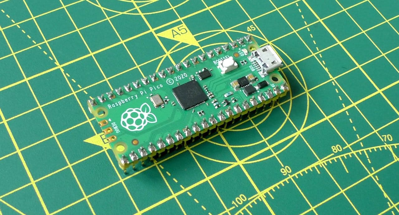
- A Raspberry Pi Pico
- These are widely available from many online electronics suppliers.
- A Waveshare Pico SIM7080 cellular modem
- You can order one direct from Waveshare .
- An HT16K33-based four-digit, seven-segment LED
- Adafruit sells a good one here .
- An MCP9808 temperature sensor
- Adafruit has one of these too .
- A micro USB cable to power the hardware and connect it to your computer.
- Some jumper wires, and either a large solderless breadboards or two smaller boards clipped together.
You will also need to install and configure Twilio's CLI tool for your platform.
The components that require soldering are the Pico, the Waveshare board, the four-digit LED, and the sensor. All you'll need to do is fix connector pins to each device and, in the case of the LED, fit the LED itself to the supplied circuit board.
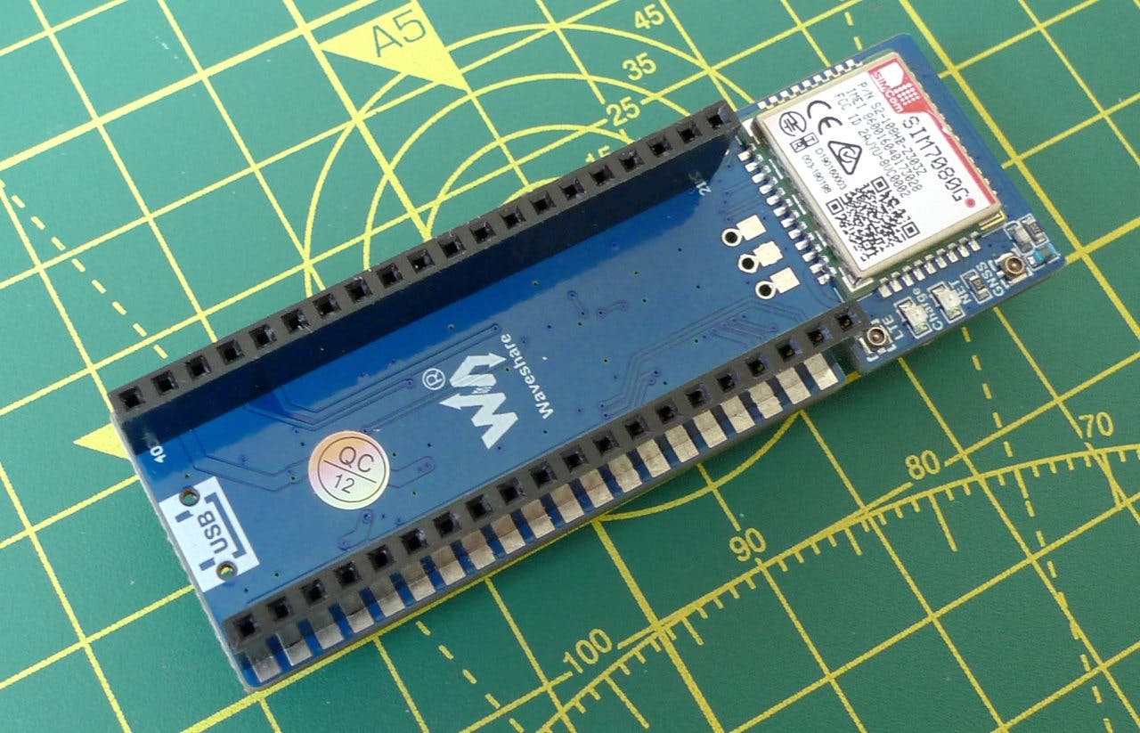
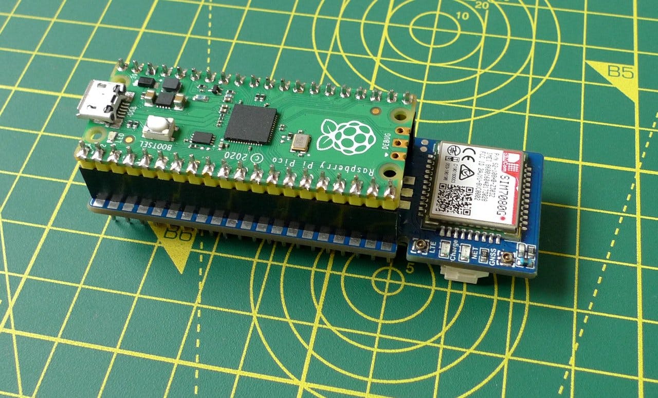
For the Waveshare Pico SIM7080, we recommend fitting the bundled female header. They're fitted with the Simcom module facing upward as shown in the picture below. You'll need to take a little extra care with the unit's GND pins because the way they're wired means they require extra heat to get the solder to flow around each pin into and into the board. If your solder is sticking to the pin but not the board, you know you haven't got the join hot enough. Place the soldering iron's tip against each of the board's GND holes for a little longer, to get it up to the right temperature.
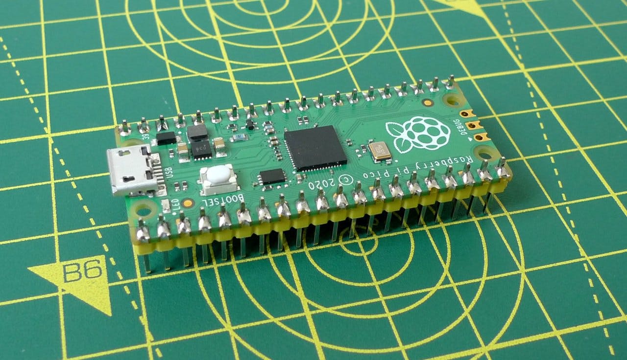
The Pico itself takes two rows of male header pins so it will slot onto the Waveshare board. You can use the header that came with the module and carefully break it into two even sections. Solder each section to one side of the Pico:
Solder the supplied header pins to the MCP9808 board. For the LED, fit and solder the LED block to the board first, clip the LED's pins, and then solder in the header pins. Make sure you orient the LED correctly: insert it into board so that the four decimal point indicators are adjacent to the 0.56" 7-segment… text on the board. Adafruit has a great guide to show you how to do this if you need more detail.

When you're done soldering, turn the Waveshare board over and fit your Super SIM into the spring-loaded slot. Push out the smallest SIM card from the Super SIM's large plastic mount. It goes in logo face up:
Now turn it back over and fit the Pico. Make sure the Pico's micro USB connector is at the opposite end to the Simcom SIM7080 module:
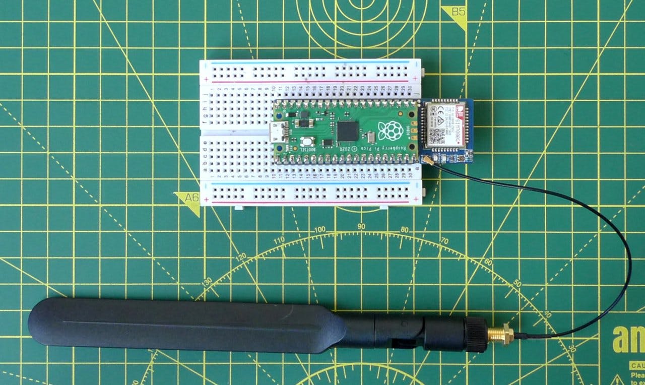
Fit the combined unit to a breadboard so you have space either side for wiring. Screw one of the thin whip cables that came with the Waveshare board into the large antenna and then clip the other end of the cable to the module's LTE connector. Take care as the U.FL antenna connector is very fragile:
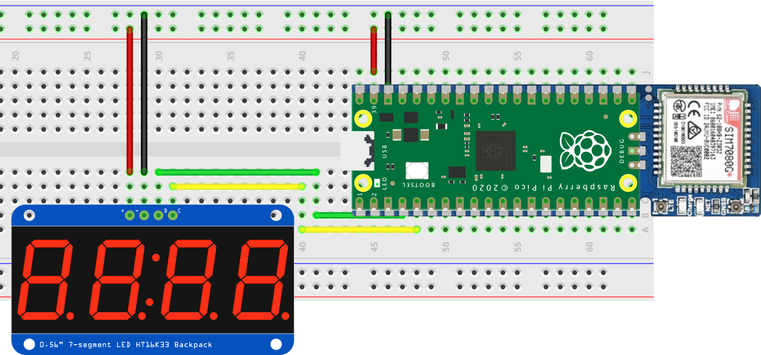
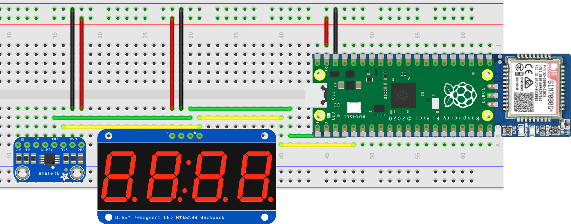
For the first part of the guide, you're going to use the four-digit LED only, so plug it into a free area of the breadboard and wire it up to the Pico using the wires like this:
-
Visit the MicroPython site and download the latest stable build for the Pico. You can
find it here
. The file will be named something like
rp2-pico-20220618-v1.19.1.uf2. - While holding down the button on the Pico marked BOOTSEL , connect the Pico to your computer with the micro USB cable. Now release the button.
- Depending on your OS, you may see a disk called
RPI-RP2mounted on your desktop, or it might appear elsewhere in your computer's file system. Copy the.uf2file you downloaded in step 1 to the drive, either by using a command-line copy program likecp, or by dragging and dropping.- Windows 10 includes drivers for UF2 devices, but earlier versions will require additional drivers to be installed. This tutorial only covers Windows 10.
- If the drive doesn't eject automatically, eject it now. Unplug it and reconnect it, this time without holding down BOOTSEL.
Select your computer's operating system from among the tabs below and follow the instructions.
- Open your distribution's terminal app.
-
Get the Pico's device file. It should be
/dev/ttyACM0. You may need to ensure you have access to the serial port: on most distributions this can be done by adding your user account to thedialoutuser group. -
You'll use a command-line serial console tool called Minicom to communicate with the Pico. Install Minicom using your operating system's package manager, such as
apt,rpm,dpkg, or similar, e.g.,sudo apt install minicom. -
Enter
minicom -o -D /dev/ttyACM0to open a connection to the module. If Minicom posts an error indicating that the device is inaccessible, check that you've connected the Pico to your computer and that you copied its device file name correctly.
You've done a lot of work to get this far, and there is plenty more to come. So take five and consider what you'll do in the remaining steps. MicroPython doesn't support the Simcom SIM7078G module directly, so you will need to write code that tells the module what you want it to do: to apply certain settings, and to transfer some information, for example.
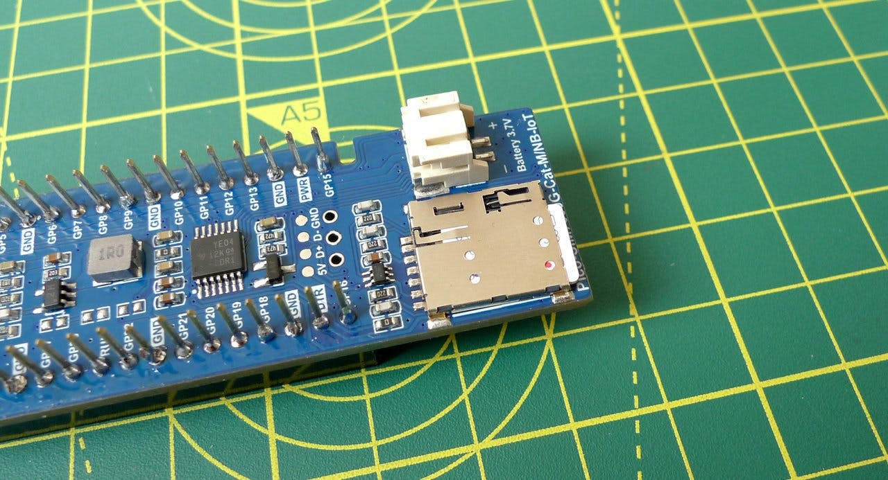
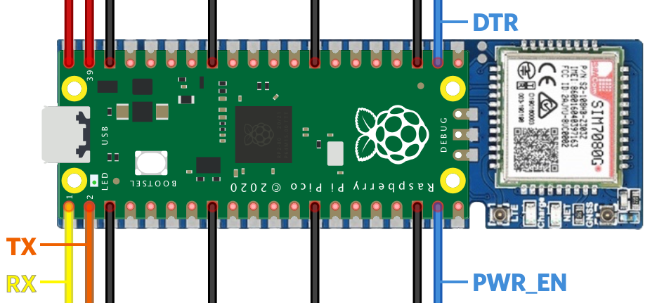
The Pico and the modem connect using four data pins, two of which are a serial link that you'll program to communicate with the module shortly. The other two are used to wake the module and to tell it to power down.
Info
These are the pins that connect the Pico and the Waveshare board. Black lines are GND; red PWR. This tutorial's code makes use of the RX, TX and PWR_EN pins.
With the communication link between MicroPython and module established, your code will send commands — called 'AT commands' — to the module and process the responses. We won't go into detail about AT commands here, but there's a good introduction available if you want to learn more. If you already know about AT commands, you can find the Simcom SIM7080's instruction set documented here. These are handy resources for further study, but you don't need to read them to complete this tutorial.
In Minicom (or PuTTY if you're using Windows 10), hit Ctrl-C to break to the Python REPL. You won't use the REPL directly, but it provides a way to enter large blocks of MicroPython code easily. Now hit Ctrl-E. This makes MicroPython ready to accept a full Python program pasted in. Click on the button at the top right of the code listing below to copy it and then paste it into Minicom. The copy button will appear when you mouse over the code. When you've pasted the code, hit Ctrl-D to tell MicroPython to run the code.
Info
You can find the a complete listing of the code, including all subsequent additions, at our public GitHub repo.
To save scrolling, click here to jump to the rest of the tutorial.
_141from machine import UART, Pin, I2C_141from utime import ticks_ms, sleep_141_141'''_141Send an AT command - return True if we got an expected_141response ('back'), otherwise False_141'''_141def send_at(cmd, back="OK", timeout=1000):_141 # Send the command and get the response (until timeout)_141 buffer = send_at_get_resp(cmd, timeout)_141 if len(buffer) > 0: return (back in buffer)_141 return False_141_141'''_141Send an AT command - just return the response_141'''_141def send_at_get_resp(cmd, timeout=1000):_141 # Send the AT command_141 modem.write((cmd + "\r\n").encode())_141_141 # Read and return the response (until timeout)_141 return read_buffer(timeout)_141_141'''_141Read in the buffer by sampling the UART until timeout_141'''_141def read_buffer(timeout):_141 buffer = bytes()_141 now = ticks_ms()_141 while (ticks_ms() - now) < timeout and len(buffer) < 1025:_141 if modem.any():_141 buffer += modem.read(1)_141 return buffer.decode()_141_141'''_141Module startup detection_141Send a command to see if the modem is powered up_141'''_141def boot_modem():_141 state = False_141 count = 0_141 while count < 20:_141 if send_at("ATE1"):_141 print("The modem is ready")_141 return True_141 if not state:_141 print("Powering the modem")_141 module_power()_141 state = True_141 sleep(4)_141 count += 1_141 return False_141_141'''_141Power the module on/off_141'''_141def module_power():_141 pwr_key = Pin(14, Pin.OUT)_141 pwr_key.value(1)_141 sleep(1.5)_141 pwr_key.value(0)_141_141'''_141Check we are attached_141'''_141def check_network():_141 is_connected = False_141 response = send_at_get_resp("AT+COPS?")_141 line = split_msg(response, 1)_141 if "+COPS:" in line:_141 is_connected = (line.find(",") != -1)_141 if is_connected: print("Network information:", line)_141 return is_connected_141_141'''_141Attach to the network_141'''_141def configure_modem():_141 # AT commands can be sent together, not just one at a time._141 # Set the error reporting level, set SMS text mode, delete left-over SMS_141 # select LTE-only mode, select Cat-M only mode, set the APN to 'super' for Super SIM_141 send_at("AT+CMEE=2;+CMGF=1;+CMGD=,4;+CNMP=38;+CMNB=1;+CGDCONT=1,\"IP\",\"super\"")_141 print("Modem configured for Cat-M and Super SIM")_141_141'''_141Flash the Pico LED_141'''_141def led_blink(blinks):_141 for i in range(0, blinks):_141 led_off()_141 sleep(0.25)_141 led_on()_141 sleep(0.25)_141_141def led_on():_141 led.value(1)_141_141def led_off():_141 led.value(0)_141_141'''_141Split a response from the modem into separate lines,_141removing empty lines and returning all that's left or,_141if 'want_line' has a non-default value, return that one line_141'''_141def split_msg(msg, want_line=99922222122222222):_141 lines = msg.split("\r\n")_141 results = []_141 for i in range(0, len(lines)):_141 if i == want_line:_141 return lines[i]_141 if len(lines[i]) > 0:_141 results.append(lines[i])_141 return results_141_141# Set up the modem UART_141modem = UART(0, 115200)_141_141# Set the LED and turn it off_141led = Pin(25, Pin.OUT)_141led_off()_141_141# Start the modem_141if boot_modem():_141 configure_modem()_141_141 # Check we're attached_141 state = True_141 while not check_network():_141 if state:_141 led_on()_141 else:_141 led_off()_141 state = not state_141_141 # Light the LED_141 led_on()_141else:_141 # Error! Blink LED 5 times_141 led_blink(5)_141 led_off()
This is the basis of the code you'll work on through the remainder of the guide. What does it do? It defines some useful functions to turn on the modem, configure the modem, and send AT commands and check the responses. It turns the Pico's LED on if it succeeds — otherwise the LED will flash five times as a signal that something went wrong: consult what's being reported in Minicom.
Info
When the code runs, it turns off the Pico's built-in LED. The LED will flash rapidly five times if there was a problem booting the modem.
The LED is turned on when the device is attached to the network. If the LED is flashing slowly, that means it has not yet attached. Please be patient; it will attach shortly, though this can take many minutes in certain circumstances.
The device code isn't doing much, so let's extend it to listen out for incoming text messages, check them for useful commands, and action any that are received.
First, though, paste the code you copied into a text editor file. You'll make quite a few changes to this as we go, and it'll be easier to do so on a text editor. You'll also be able to grab the code at each stage and paste the latest version into Minicom and over to the Pico.
With the code in your editor, paste the following right after the final function definition, def split_msg(msg, want_line=99):
_44'''_44Extract the SMS index from a modem response line_44'''_44def get_sms_number(line):_44 p = line.split(",")_44 if len(p) > 0:_44 return p[1]_44 return 0_44_44'''_44Blink the LED n times after extracting n from the command string_44'''_44def process_command_led(msg):_44 blinks = msg[4:]_44 print("Blinking LED",blinks,"time(s)")_44 try:_44 led_blink(int(blinks))_44 except:_44 print("BAD COMMAND:",blinks)_44_44'''_44Listen for incoming SMS Commands_44'''_44def listen():_44 print("Listening for Commands...")_44 while True:_44 # Did we receive a Unsolicited Response Code (URC)?_44 buffer = read_buffer(5000)_44 if len(buffer) > 0:_44 lines = split_msg(buffer)_44 for line in lines:_44 if "+CMTI:" in line:_44 # We received an SMS, so get it..._44 num = get_sms_number(line)_44 msg = send_at_get_resp("AT+CMGR=" + num, 2000)_44_44 # ...and process it for commands_44 cmd = split_msg(msg, 2)_44 if cmd.startswith("LED="):_44 process_command_led(cmd)_44 else:_44 print("UNKNOWN COMMAND:",cmd)_44 # Delete all SMS now we're done with them_44 send_at("AT+CMGD=,4")
Now add this line right after #Light the LED and led_on() in the section headed # Start the modem:
_10# Begin listening for commands_10listen()
Copy all the code. Go back to Minicom and you should see the >>> prompt. Hit Ctrl-E, paste in the new Python, and then hit Ctrl-D to run it.
This time, you won't see >>> in Minicom but rather the line Listening for Commands.... The Pico is waiting for instructions — let's send it something.
Info
If you get tired of all this cutting and pasting, grab the MicroPython utility Pyboard. Save it to your computer and make the file executable. You can then call it as follows:
Linux/macOS
_10python pyboard.py -d /dev/ttyACM0 -f cp my_code.py :main.py
Windows 10
_10python pyboard.py -d COM3 -b 9600 -f cp my_code.py :main.py
where my_code.py is the saved version of the code you're assembling in your text editor. Mac users wlll need to change the device file name. Windows 10 users shoud confirm their device COM port and quit PuTTY if it's still running.
Pyboard will transfer the code to the Pico and present the program's output. It can also be used to transfer files to the Pico's filesystem, but we're not going to need that functionality here. You can read more about Pyboard's features at the MicroPython docs website.
Open up a new terminal window or tab (or open Command Prompt in Windows) and paste in the following command:
_10twilio api:supersim:v1:sms-commands:create \_10 --sim "<YOUR_SIM_NAME_OR_SID>" \_10 --payload "LED=10"
Info
Windows 10 folk, when you copy the example above — and others later on — make sure you either remove each `` so all the elements are on the same line, or replace them with a ^ and a space. The space is important: Windows won't recognize the command as a multi-line entry without it.
You'll need to replace the sections in angle brackets (< and >) with your own information. Your SIM's SID — or friendly name if you've set one — and the specified account credentials are all accessible from the Twilio Console.
This command uses the Super SIM API's SMS Commands feature to send a machine-to-machine message to the Pico by way of the cellular module and its Super SIM. The key part is the --payload "LED=10" part. The payload parameter tells Twilio to send the portion in the double-quotes as the body of the message. In this case, that's LED=10.
The listen() function in your Python code keeps an ear open for incoming SMS messages, which are signaled by the module transmitting a string that includes the characters +CMTI. If it appears, the code sends a new AT command to the modem to get the message (AT+CMGR) and then awaits a response. When the response comes, the code processes it and extracts the LED=10 — which tells the device to flash its LED ten times.
Flashing the LED is a good start, but you can't use it to display readily readable informations. Let's make use of the four-digit display so show some values in bold color.
The display needs code to drive it. Rather than include it all here, just grab the code you need from this public GitHub repo. You'll need the contents of two files — click the links below to view the raw code in your browser, then copy and paste each one into your text editor, right below the import statements at the top.
Warning
With the second file, make sure you only copy the class — don't include the first two lines above it (starting # Import the base class...)
You also need to add the following functions further down, and make some changes to listen(). So just copy the following code and use it to replace all of your existing listen() function:
_43'''_43Display the decimal value n after extracting n from the command string_43'''_43def process_command_num(msg):_43 value = msg[4:]_43 print("Setting",value,"on the LED")_43 try:_43 # Extract the decimal value (string) from 'msg' and convert_43 # to a hex integer for easy presentation of decimal digits_43 hex_value = int(value, 16)_43 display.set_number((hex_value & 0xF000) >> 12, 0)_43 display.set_number((hex_value & 0x0F00) >> 8, 1)_43 display.set_number((hex_value & 0x00F0) >> 4, 2)_43 display.set_number((hex_value & 0x000F), 3).update()_43 except:_43 print("BAD COMMAND:",value)_43_43'''_43Listen for incoming SMS Commands_43'''_43def listen():_43 print("Listening for Commands...")_43 while True:_43 # Did we receive a Unsolicited Response Code (URC)?_43 buffer = read_buffer(5000)_43 if len(buffer) > 0:_43 lines = split_msg(buffer)_43 for line in lines:_43 if "+CMTI:" in line:_43 # We received an SMS, so get it..._43 num = get_sms_number(line)_43 msg = send_at_get_resp("AT+CMGR=" + num, 2000)_43_43 # ...and process it for commands_43 cmd = split_msg(msg, 2)_43 if cmd.startswith("LED="):_43 process_command_led(cmd)_43 elif cmd.startswith("NUM="):_43 process_command_num(cmd)_43 else:_43 print("UNKNOWN COMMAND:",cmd)_43 # Delete all SMS now we're done with them_43 _ = send_at("AT+CMGD=,4")
Finally, add the following lines after the # Setup the modem UART block:
_10# Set up I2C and the display_10i2c = I2C(1, scl=Pin(3), sda=Pin(2))_10display = HT16K33Segment(i2c)_10display.set_brightness(2)_10display.clear().draw()
Copy all the new code from your text editor and paste it to the Pico in the usual way.
Now send a slightly different command via SMS:
_10twilio api:supersim:v1:sms-commands:create \_10 --sim "<YOUR_SIM_NAME_OR_SID>" \_10 --payload "NUM=2021"
Again, you'll need to do this in a separate terminal tab or window, and replace the <...> sections with your own data.
After a moment or two you should see 2021 appear on the LED. If it doesn't appear after a short time, check you have the LED wired to the Pico correctly — take a look at the diagram above. If you see Setting 2021 on the LED in Minicom, you know the command was received. If not, did you enter the command above correctly? Perhaps you mis-typed the payload value. You'll see an error message in Minicom in this case.
It should be clear what's happening: the code dissects the incoming text message for a command and a value. Before, only the LED command was supported; now so is NUM. For the latter, the value is written to the display.
Now it's time to make the conversation two way.
Slot the MCP9808 temperature sensor into the breadboard and wire it up as follows:
We've shown an expanded layout to make clear where the connections go, but you can adjust it as you prefer, especially if you're working with a smaller breadboard.
Now for the code. Add the sensor's driver code — paste all of the following code after the import statements at the top:
_28class MCP9808:_28 """_28 A simple driver for the I2C-connected MCP9808 temperature sensor._28 This release supports MicroPython._28 """_28_28 # *********** PRIVATE PROPERTIES **********_28_28 i2c = None_28 address = 0x18_28_28 # *********** CONSTRUCTOR **********_28_28 def __init__(self, i2c, i2c_address=0x18):_28 assert 0x00 <= i2c_address < 0x80, "ERROR - Invalid I2C address in MCP9808()"_28 self.i2c = i2c_28 self.address = i2c_address_28_28 # *********** PUBLIC METHODS **********_28_28 def read_temp(self):_28 # Read sensor and return its value in degrees celsius._28 temp_bytes = self.i2c.readfrom_mem(self.address, 0x05, 2)_28 # Scale and convert to signed value._28 temp_raw = (temp_bytes[0] << 8) | temp_bytes[1]_28 temp_cel = (temp_raw & 0x0FFF) / 16.0_28 if temp_raw & 0x1000: temp_cel -= 256.0_28 return temp_cel
Add the following function below the def process_command_num(msg): function definition:
_12'''_12Get a temperature reading and send it back as an SMS_12'''_12def process_command_tmp():_12 print("Sending a temperature reading")_12 celsius_temp = "{:.2f}".format(sensor.read_temp())_12 if send_at("AT+CMGS=\"000\"", ">"):_12 # '>' is the prompt sent by the modem to signal that_12 # it's waiting to receive the message text._12 # 'chr(26)' is the code for ctrl-z, which the modem_12 # uses as an end-of-message marker_12 r = send_at_get_resp(celsius_temp + chr(26))
Add these lines to the command checking sequence within the listen() function:
_10elif cmd.startswith("TMP"):_10 process_command_tmp()
Finally, you need to instantiate the sensor for use, so add these lines below the # Set up I2C and the display block:
_10# Set up the MCP9808 sensor_10sensor = MCP9808(i2c=i2c)
Once again, copy all the source code from your editor and paste it over to the Pico. Assuming you made no text entry or pasting errors, the code will run, and you'll shortly see Listening for Commands… as usual.
Your device is now ready to receive TMP commands, which will cause it to send an SMS Command containing the current temperature of the air around it. But you're not quite ready to send the command yet: you need to configure your Super SIM's fleet to relay device-originated messages to your server.
The SMS Commands API provides a specific phone number, 000, to which all SMS messages, from every device, are sent. Twilio relays the ones it has received from your SIMs on to you. How does it know exactly where to send them? You specify a webhook address.
Super SIMs are organized into Fleets: groups of SIMs that have common settings, such as which networks they are able to connect to and whether they can make use of cellular data services. Fleets are represented in the Super SIM API by Fleet resources, and SMS Commands adds properties to each Fleet resource in which you can store your SMS Commands webhook address and, optionally, the HTTP method it uses.
So before you can send a message from the device, you need to set up a webhook target URL and add it to your Super SIM's Fleet.
Beeceptor is a handy service for testing webhooks. It's designed for developing and testing APIs of your own, and offers free mock servers — virtual endpoints that can receive webhook calls. Let's set one up to receive messages from the device.
- In a web browser tab, go to Beeceptor .
-
Enter an endpoint name in the large text field and click Create Endpoint:

-
On the screen that appears next, click on the upper of the two clipboard icons to copy the endpoint URL:

- Keep the tab open.
Now you update your Super SIM's Fleet to add an SMS Commands webhook. You can do this with the API, but we'll use the Console for this demo.
- Open a second web browser tab and log into the Console .
- Go to IoT > Super SIM > Fleets and select the Fleet containing the Super SIM you are using.
-
Scroll down to SMS Commands Callback URL and paste in your webhook URL from the previous section. By default, webhooks are triggered with a
POSTrequest. Leave it unchanged for now, but if you need to use another method for your own application, you can change it later:
- Click Save .
- Close the tab if you like.
In a new terminal tab or window, send this API command:
_10twilio api:supersim:v1:sms-commands:create \_10 --sim "<YOUR_SIM_NAME_OR_SID>" \_10 --payload "TMP"
Again, you'll need to replace the <...> sections with your own settings.
-
Jump back to the Beeceptor tab in the browser. You should see — or will shortly see — the endpoint has received a
POSTrequest. Click on it to see the request body, then on the JSON icon, {:} , to view the data more clearly. -
Look for the line beginning
Payload=— right after it is the temperature as sent by your device:
- Read the temperature measured by the device's sensor.
Well done! You've come a long way, but you now have a Raspberry Pi Pico that can communicate with an attached Simcom SIM7080 modem. It can receive and parse commands relayed using Super SIM's SMS Commands array to activate its LED and a connected display. It can retrieve readings from a connected temperature sensor peripheral, and send them back to base — again via SMS Commands. In short, you have an IoT device with two-way communication with your server-side application.
That's not the end of the process. For a start, you have to build that very server-side application. You might also want to produce a mobile or web app to allow your end-users to control elements of your IoT product themselves.
That's in the future, though. For now, you may want to consider ways to expand the testbed you've built today. Try adding some other sensors, output devices, or actuators to allow the unit to affect the physical world.
The code doesn't check connection state. Tell the modem to send you cellular registration notifications and update the listen() function to watch form the. Our guide Four Best Practices for Cellular Module Registration has guidance to help you.
The current command processor is basic — why not try to extend it to support commands, data, and other information, such as timestamps, via a JSON package? Hint: use an encoding technique like base 64 to convert your JSON strings into characters within the 7-bit SMS character set. Third-party libraries can help you with this.
You might also want to allow the device to communicate with Internet-hosted resources directly, to GET or POST data. We're going to cover just that in an upcoming tutorial based on the device you assembled and got running today.
Wherever you take your Raspberry Pi Pico-based IoT device next, we can't wait to see what you build!
Info
Check out our follow-up tutorial: Get Started with Super SIM: Raspberry Pi Pico Data Comms.